-NCC.74656 Voyager-
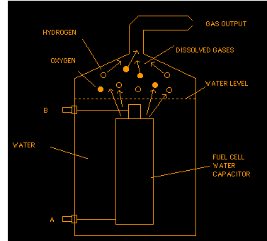
WATER FUEL CELL
In brief, the water fuel cell is a method of obtaining the release of
a gas mixture including hydrogen and oxygen and other dissolved gases formerly
entrapped in water. In the process, the point of optimum gas release is
reached at a circuit resonance. Water in the fuel cell is subjected to a
pulsating, polar electric field produced by the electrical circuit whereby
the molecules begin to break apart. The polar pulsating frequency applied
is such that the pulsating electric field induces a resonance in the molecule.
A cascade effect occurs and the overall energy level of specific water molecules
is increased in cascading, incremental steps. The hydrogen and oxygen atomic
gases, and other gas components formerly entrapped as dissolved gases in
water, are released when the resonant energy exceeds the co-valent bonding
force of the water molecule. A preferred construction material for the capacitor
plates is stainless steel T-304 which is non-chemical reactive with water,
hydrogen, or oxygen. An electrically conductive material which is inert
in the fluid environment is a desirable material of construction for the
electrical field plates of the "water capacitor" employed in the circuit.
Once triggered, the gas output is controllable by the reduction of the
operational parameters. Once the frequency of resonance is identified the
gas output can be varied. Changing of the voltage field frequency in the
form of OFF and ON pulses also affects the output. When a unipolar voltage
pulse is applied to positive and negative capacitor plates, an increasing
voltage potential is induced in the molecules in a linear, step like charging
effect. The electrical field of the particles within a volume of water including
the electrical field plates increases from a low energy state to a high
energy state. In the first stage of the process the voltage pulse causes
initially randomly oriented water molecules in the liquid state to spin
and orient themselves with reference to positive and negative poles of the
voltage fields applied. The positive electrically charged hydrogen atoms
of the water molecule are attracted to a negative voltage field, but at the
same time, the negative electrically charged oxygen atoms of the same water
molecule are attracted to a positive voltage field. As the water molecule
is further exposed to an increasing potential difference resulting from
the step charging of the capacitor, the electrical force of attraction of
the atoms within the molecule to the capacitor plates of the chamber also
increase in strength. As a result, the co-valent bonding between which form
the molecule is weakened - and ultimately terminated. The negatively charged
electron is attracted toward the positively charged hydrogen atoms, while
at the same time, the negatively charged oxygen atoms repel electrons.
When a volume of water is isolated and electrically conductive plates, that
are chemically inert in water and are separated by a distance, are immersed
in water, a capacitor is formed, having a capacitance determined by the
surface area of the plates, the distance of their separation and the dielectric
constant of water. When a charge is applied to a capacitor, the electrical
charge of the capacitor equals the applied voltage charge; in a water capacitor,
the dielectric property of water resists the flow of amps in the circuit.
In the Example of a fuel cell circuit of FIG. 1, a water capacitor is included.
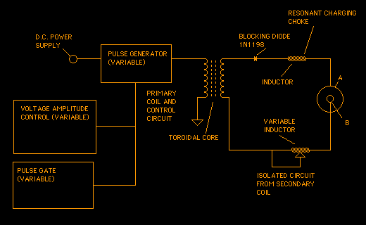
The step-up coil is formed on a conventional torroidal core formed of
a compressed ferromagnetic powered material that will not itself become permanently
magnetized. The core is 1.50 inch in diameter and 0.25 inch in thickness.
A primary coil of 200 turns of 24 gauge copper wire is provided and coil
of 600 turns of 36 gauge wire comprises the secondary winding. In the circuit
of FIG 1, the diode is a 1N1198 diode which acts as a blocking diode and an
electric switch that allows voltage flow in one direction only. Thus, the
capacitor is never subjected to a pulse of reverse polarity. The primary
coil of the torroid is subject to a 50% duty cycle pulse. The torroidal pulsing
coil provides a voltage step-up from the pulse generator in excess of five
times, although the relative amount of step-up is determined by pre-selected
criteria for a particular application. As the stepped-up pulse enters the
first inductor (formed from 100 turns of 24 gauge wire 1 inch in diameter),
an electromagnetic field is formed around the inductor, voltage is switched
off when the pulse ends, and the field collapses.
Note:
1N1198 Diode is also a NTE 5995 or a ECG 5994. It is a 40A 600 PIV Diode
(the 40A is over kill and may not be needed).
Stainless Steel T-304 is a type of weldable Stainless, but other types
should work the same. T-304 is just the more common type of Stainless
tubing available. The outer tube figures out to be 3/4" 16 gauge (.060 "wall")
tube (a common size) cut to 4 inch length. The inner tube figure out to
be 1/2" 18 gauge (.049 thickness, this is a common size for this tube) cut
to 4 inch length. You should also attach the two leads to the Stainless,
using Stainless solid rod (1/6 diameter would do) and USE LEAD FREE SOLDER
!